ESP32 Swimming Pool Monitor
A 20x4 LCD, a PIR sensor, a water temperature probe and a float sensor on the wall by my pool - and the WiFi problem that beat me for two and a half years before ESPHome finally sorted it out.
There has been a screen on the wall next to my pool since December 2023. It has caused me more grief than anything else I have ever built, and it has also been quietly useful every single day for two and a half years. That combination is why it is still there.
This is the story of my ESP32 swimming pool monitor: a 20x4 LCD, a pile of sensors, a rotary encoder I eventually gave up on, and a WiFi problem that I lost to for a very long time before I finally won.
What the thing actually is
A box on the wall by the pool. Walk past it, and it tells you what the water is doing:
- A 20x4 blue character LCD — four lines, twenty characters each
- A PIR sensor, so the backlight comes on when you walk up to it and goes off again when you walk away
- A waterproof DS18B20 temperature probe, sitting in the pool water
- A DHT22 for the ambient temperature and humidity
- A float sensor, to tell me when the pool water level drops too low
- A clickable rotary encoder — too much on that later, because it is the bit that did not survive
- An ESP32 devkit doing all the thinking — an ESP32-WROOM-32, sitting on a protoboard I soldered myself, and the classic
esp32devboard in the sketch further down
It started life in a small black off-the-shelf project box, and I cut every opening in that one myself with a Dremel — the window for the LCD, the holes for the sensors, and terminal connectors on the side so the wires to the pool can be disconnected without opening the box.
The original idea was far bigger than what survived
When I started this, I wasn’t building a pool thermometer. I was building a little control panel for the house, and I spent days on it.
The idea was custom menus, browsable with the rotary encoder. A home page showing the date and time from an NTP server, the pool temperature, and the ambient temperature and humidity. Then pages behind that — stats for the home, a way to switch on the irrigation, the lights, and control the pool pump.
Here is what that actually looked like while I was building it — the LCD mounted in the front panel of that off-the-shelf box, with the breadboard still sitting behind it and the rotary encoder on a blue knob:
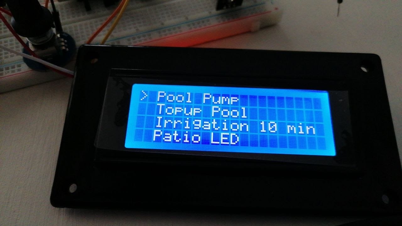
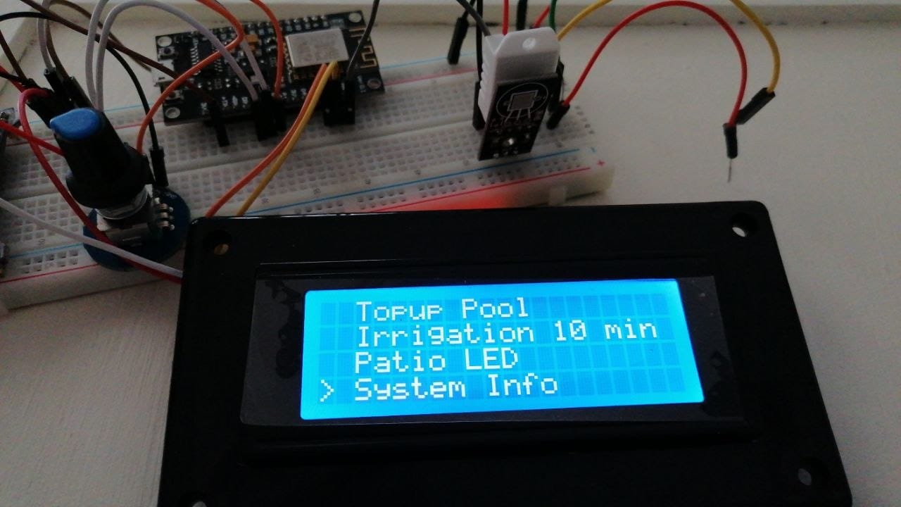
The menu read Pool Pump, Topup Pool, Irrigation 10 min, Patio LED and System Info, with that little arrow scrolling up and down the list as I turned the encoder. Every one of those did something real: run the pump, top the pool up, start a ten minute irrigation cycle, switch the patio lights, and read back what the rest of the house was doing. That is a long way from a pool thermometer, and it is why losing all of it later stung as much as it did.
Here it is actually running on the breadboard, with the encoder being turned through the pages:
The breadboard prototype: the home page, the menu scrolling with the encoder knob, and the info page
I had a lot of fun writing those menus. That was the part of the project I actually enjoyed most, and it is worth saying out loud now because of what I eventually did with it, which was throw it away.
Breadboard, then my own PCB, and it all worked
I breadboarded the whole thing first and it worked. So I soldered up my own DIY PCB — a protoboard, if you want to be particular about it, and you can see it in the photos further down — and that worked too. Both of those statements matter, so hold onto them.
Then I closed the lid
The minute I closed the project box, the ESP32 would not connect to WiFi.
Open the box, and it connects instantly. Every single time. Close it, and it is dead to the world.
I spent months on this. I asked on ESP forums. I went down every rabbit hole I could find, and I kept coming back to the LCD and the I2C protocol — some interference or timing problem I could not pin down. Eventually I settled on a theory: the LCD was sitting right on top of the ESP32 in that box, and something about that was killing the radio.
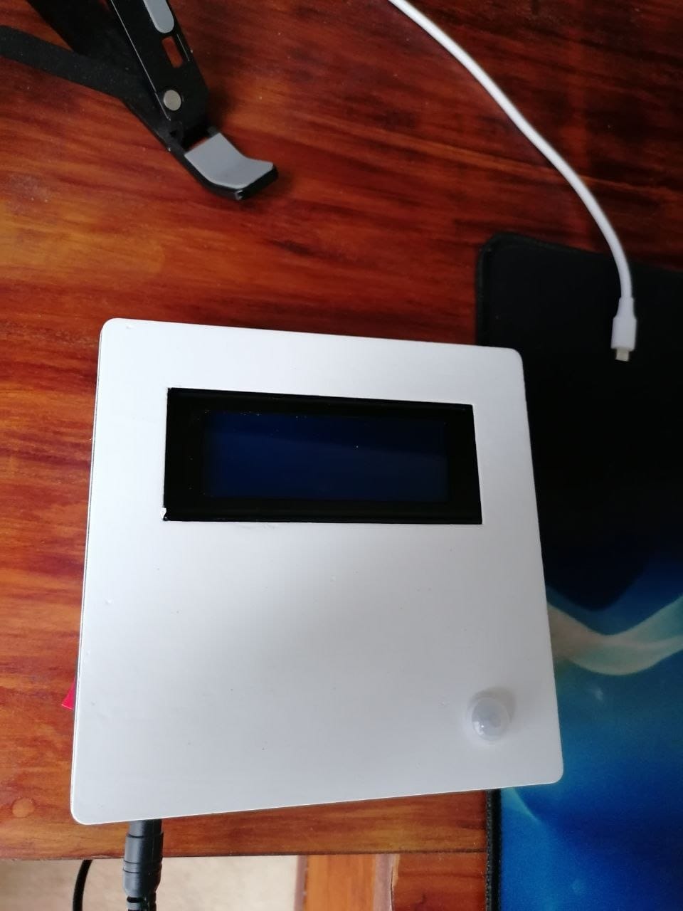
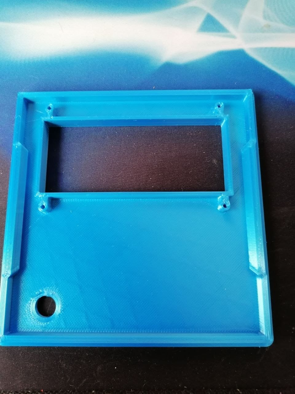
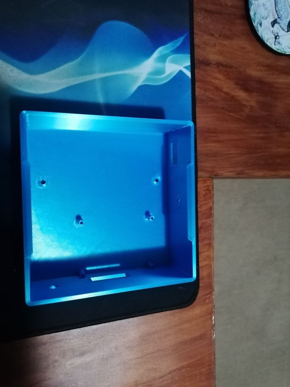
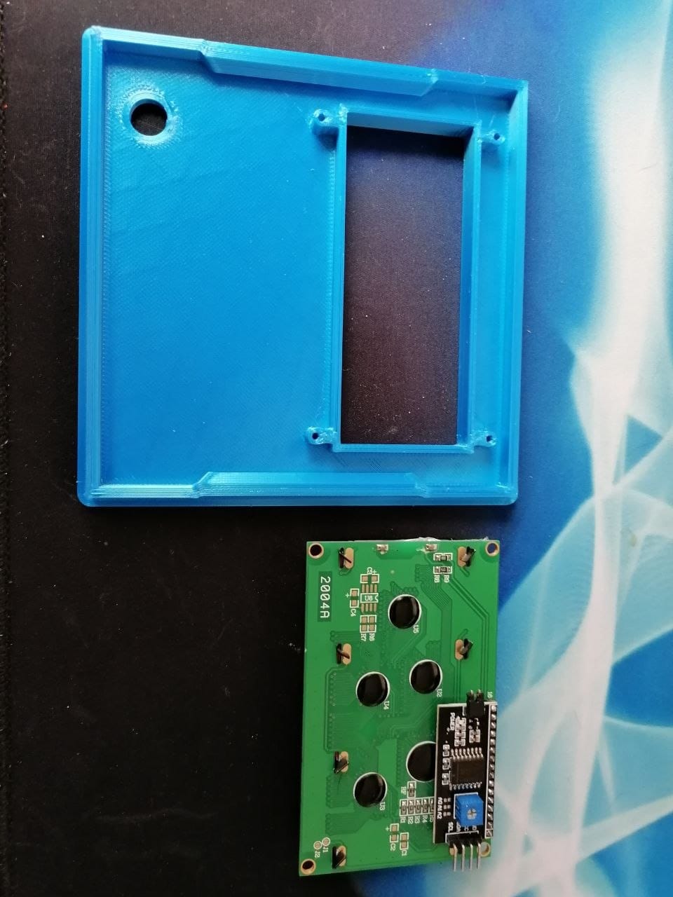
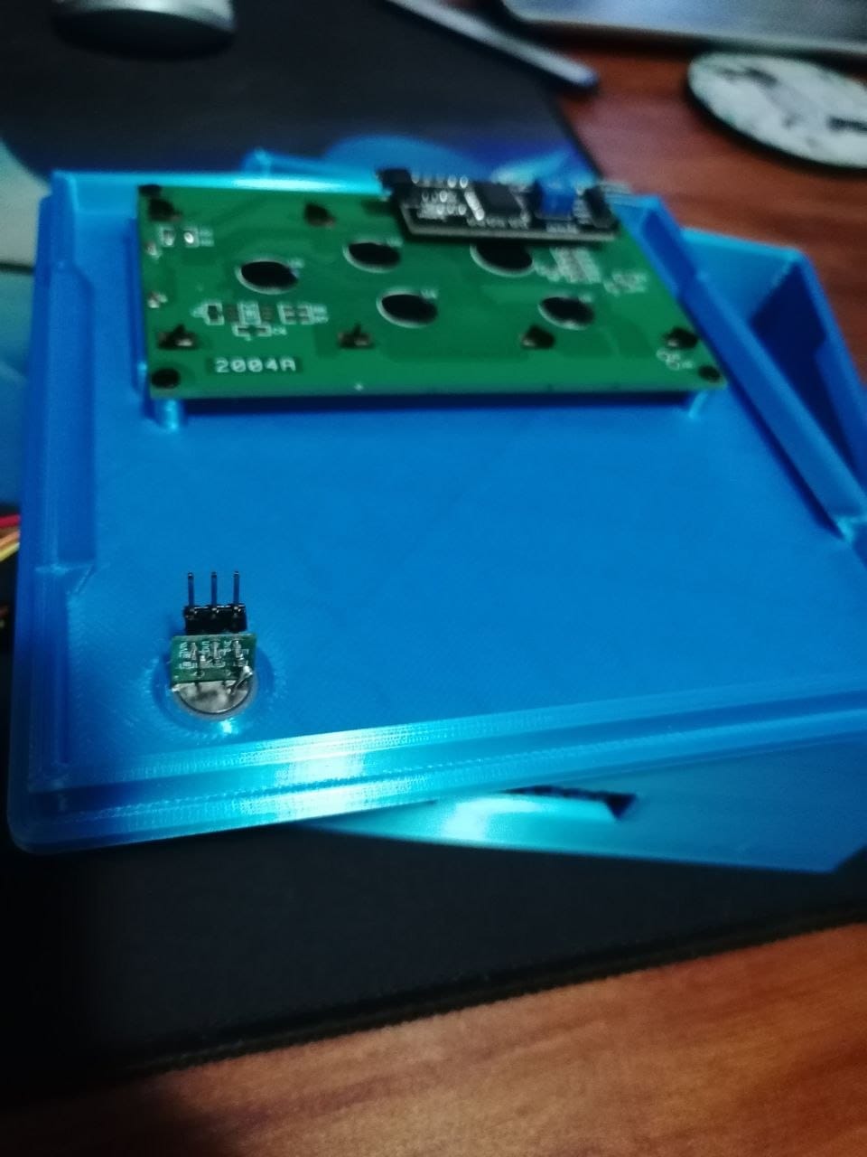
So I designed and 3D printed a custom box. Deliberately bigger than it needed to be, so the ESP32 could be moved down and away, sitting side by side with the LCD instead of directly underneath it. It came off the printer in blue, and I painted the outside of it white later on — PLA does not take kindly to the sun and the weather, and this box lives outside next to a pool.
The screen and the encoder were never the problem. Here it is in the new box, working its way through the same menus:
The menus running in the blue 3D printed enclosure, with the info page showing version 2023.12
It still failed.
That was the point where I stopped trying to solve it and started trying to live with it.
Two and a half years of the compromise version
I stripped the project back to a plain Arduino sketch. Just read the sensors and put them on the screen. No NTP, so no clock and no timestamp. No WiFi. No home automation.
And that is how it ran, mounted on the wall, for years. It was genuinely useful and I was never happy with it, which is a combination I have got quite good at living in.
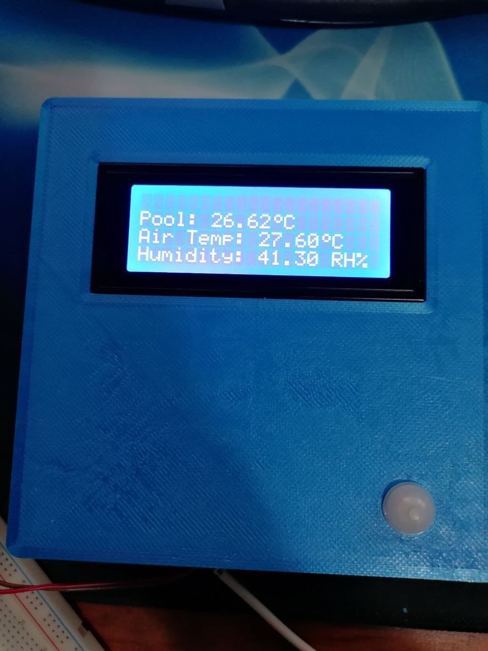
And here it is where it actually lived, in the 3D printed box after I painted it, in the years when it was reporting to nobody at all:
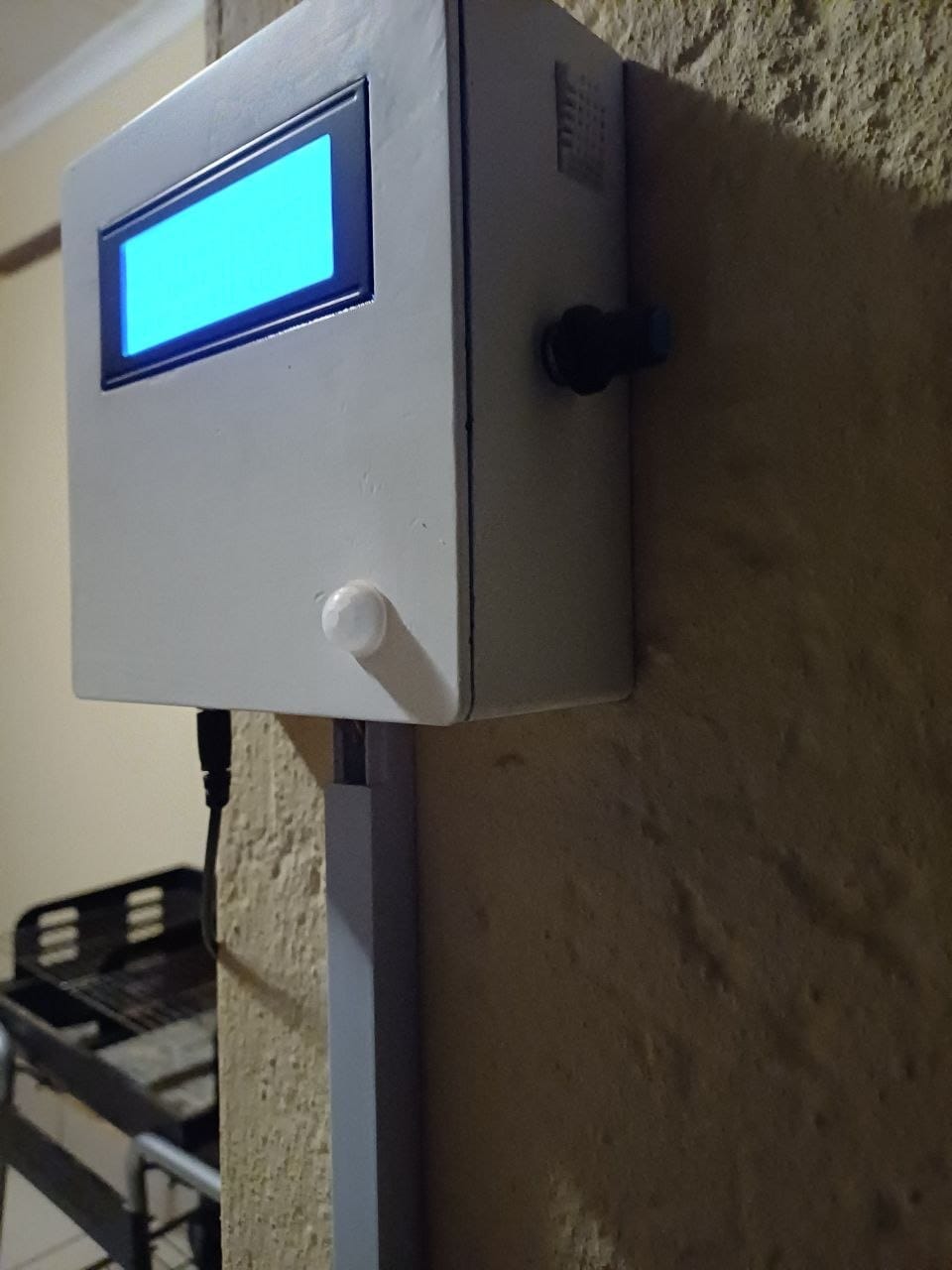
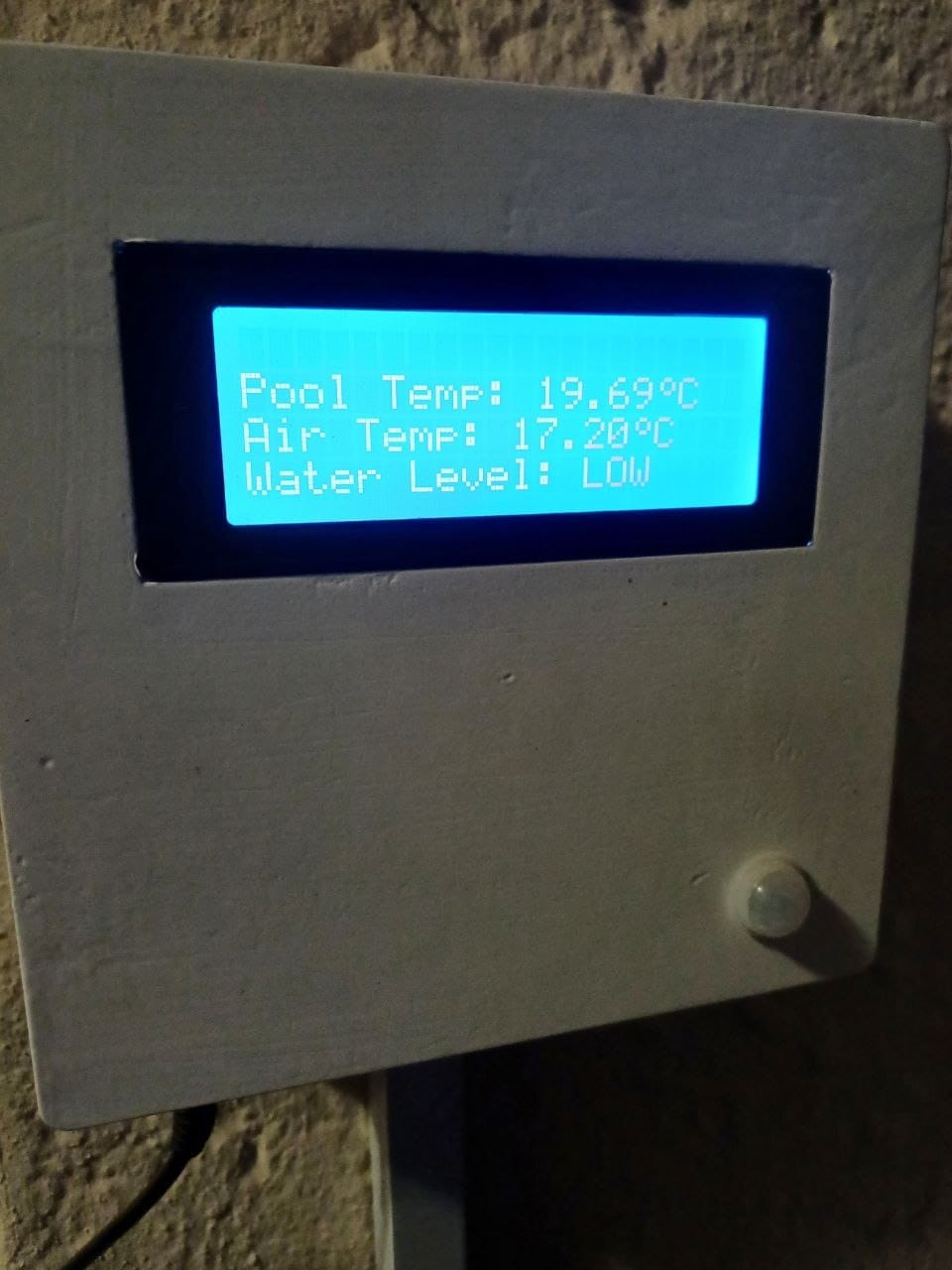
That is the whole compromise in two photos. Pool temperature, air temperature, and a water level off the float sensor — everything this project is for, on a screen you can read at a glance, and not one byte of it going anywhere.
The plumbing half of the project
There is a part of this build that has nothing to do with electronics.
The pool water level drops over time — that is just what a pool does in this climate — so the monitor needed a way to top it up. I cut a groove into the paving and ran a water pipe out to the pool, fed from an irrigation valve. Alongside that pipe I ran the wires for the temperature probe and the float sensor, all held in place by a bracket I 3D printed to clamp them to the pipe.
Here is that end of the project. The bracket started life as a model on my laptop — a clamp that wraps around the fill pipe, with a hole for the temperature probe and a seat for the float switch — and ended up as the little white assembly hanging in the water off the end of the pipe:
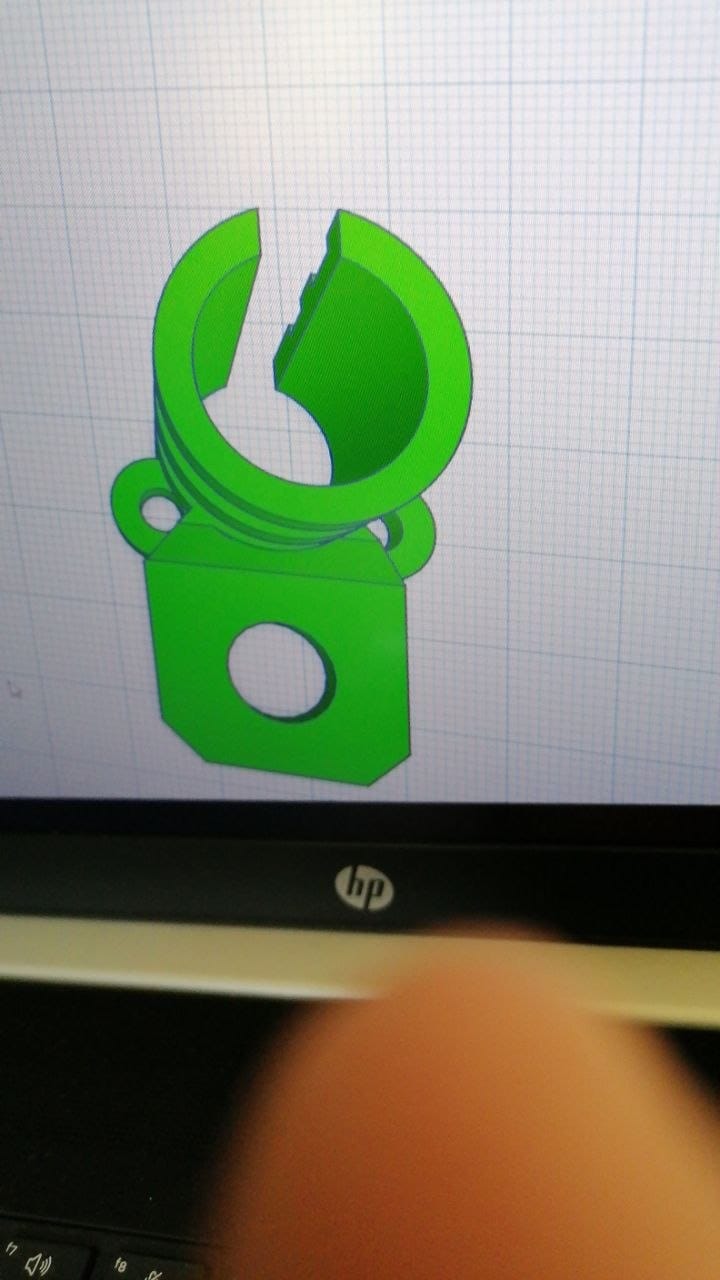
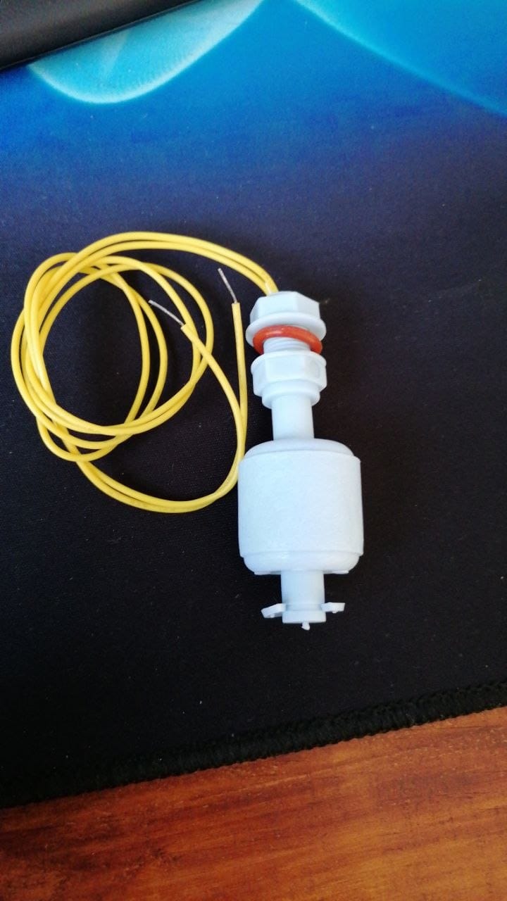
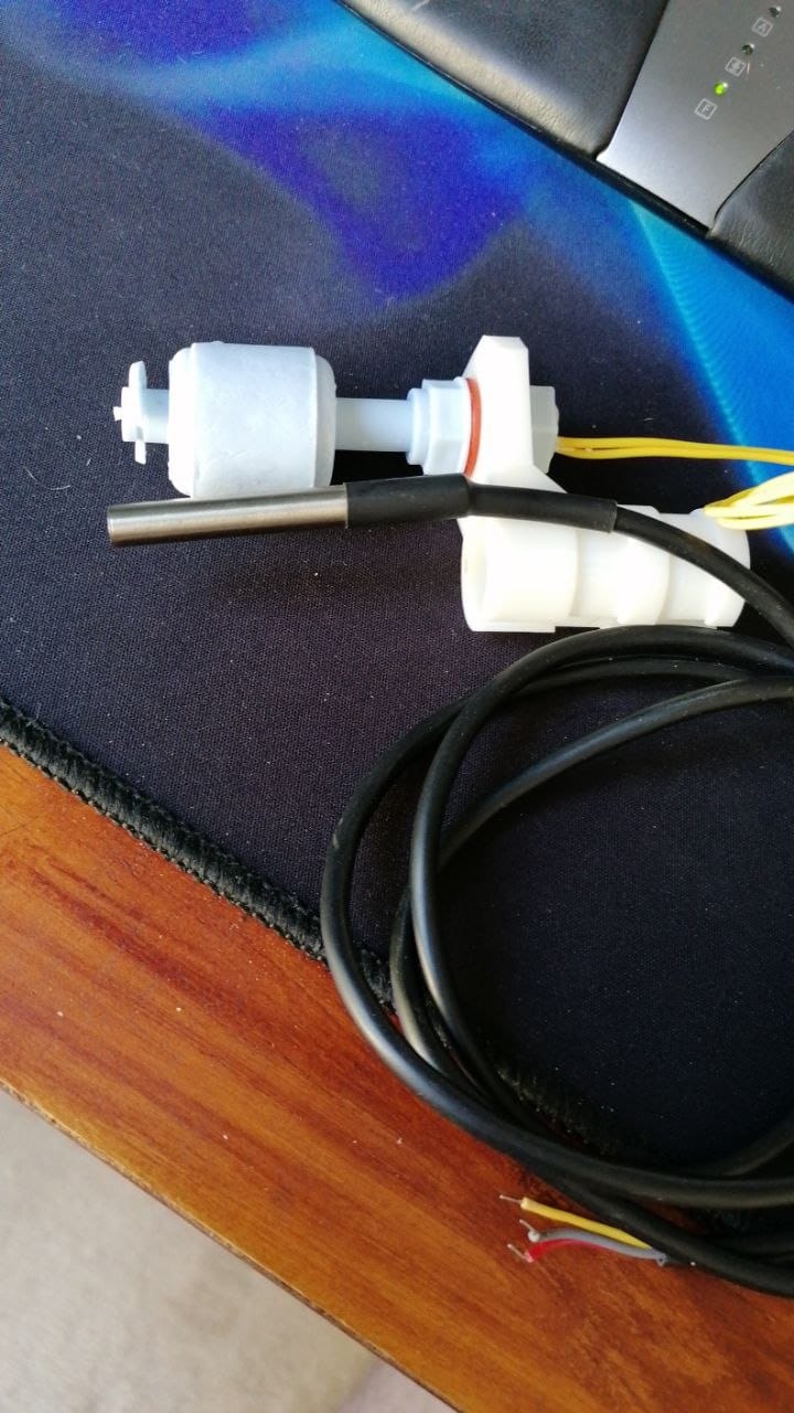
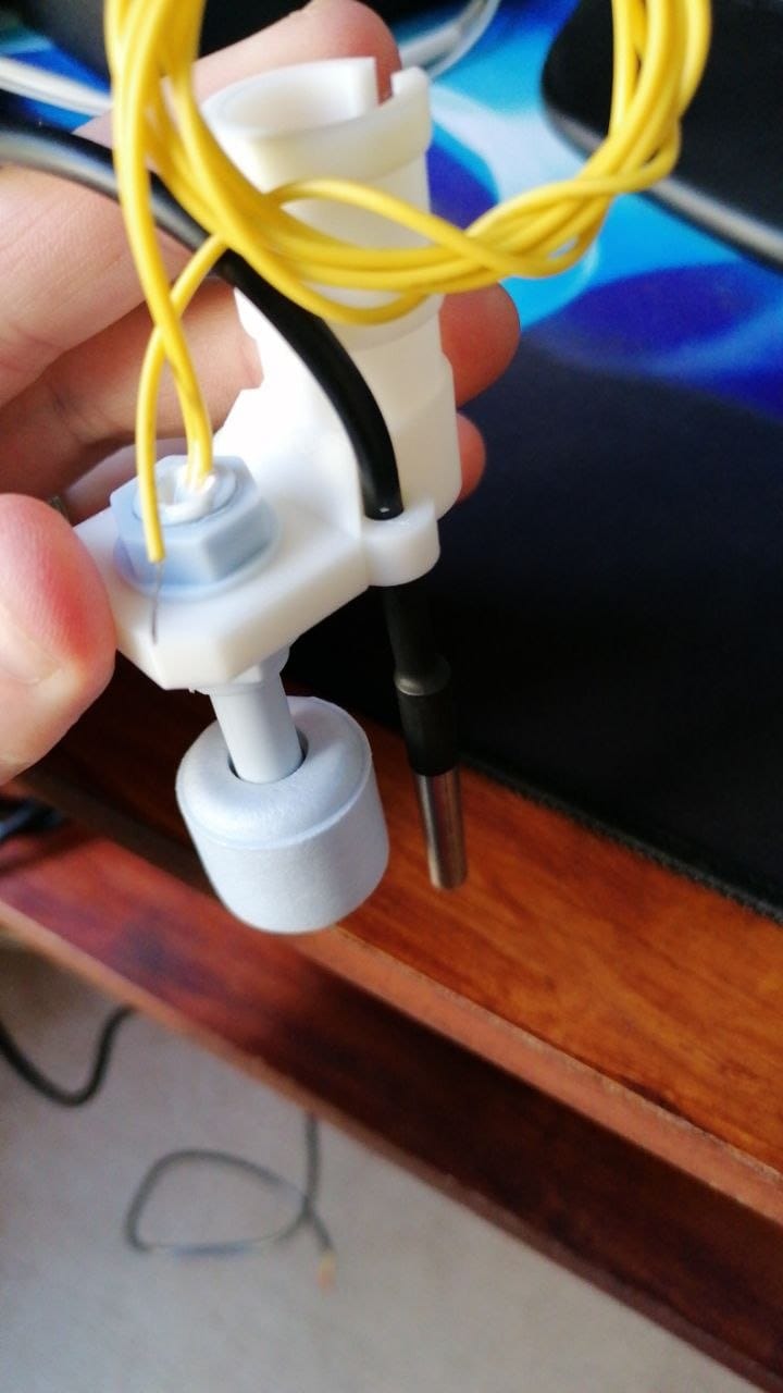
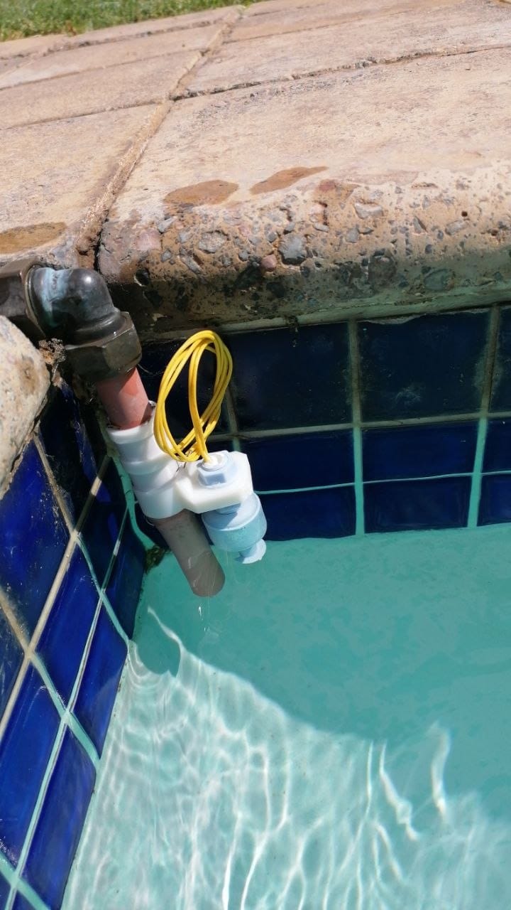
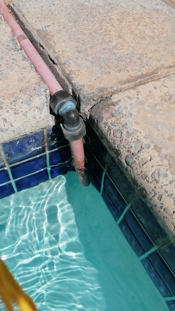
Those two sensors do the whole job down at that end. The float switch tells me whether the water has dropped far enough to matter, and the probe beside it tells me whether the pool is worth getting into. Both of them run back along the pipe, through that groove in the paving, to the box on the wall.
So the valve fills the pool, and the float sensor tells the system when the water has dropped far enough to need it. The plan from the beginning was that it would top itself up on its own, with a manual route for the times I want to take control by hand — that is exactly what the Topup Pool entry in the menu was there for. If you are interested in the electrical side of the pool — the pump, the light, the water feature, and rewiring the lot into an outdoor DB board — that is an older story of its own.
Coming back to it, years later
I built this thing back when I was still running OpenHAB as my home server. Since then I moved everything to Home Assistant, and more recently I migrated the house to Tasmota and then to ESPHome — about thirty odd devices in a single day, which I wrote about separately.
The pump went the same way, incidentally. It has been on a Sonoff POW R2 with its energy monitoring chip since that older post, and it is its own ESPHome device now — so I can see exactly what the pump is drawing, and the run schedule lives in Home Assistant with everything else. Which left the monitor sitting there as the only thing in the house still running an old standalone sketch.
So the pool monitor started nagging at me. It was the last device in the house running an old stripped-down sketch with no connection to anything. So I had a thought: what if ESPHome somehow fixes the connection problem? Same chip, same board, same sensors, but a completely different stack underneath.
I grabbed my laptop, flashed it in place while it was still mounted to the wall, closed it up, and waited.
It still did not connect properly.
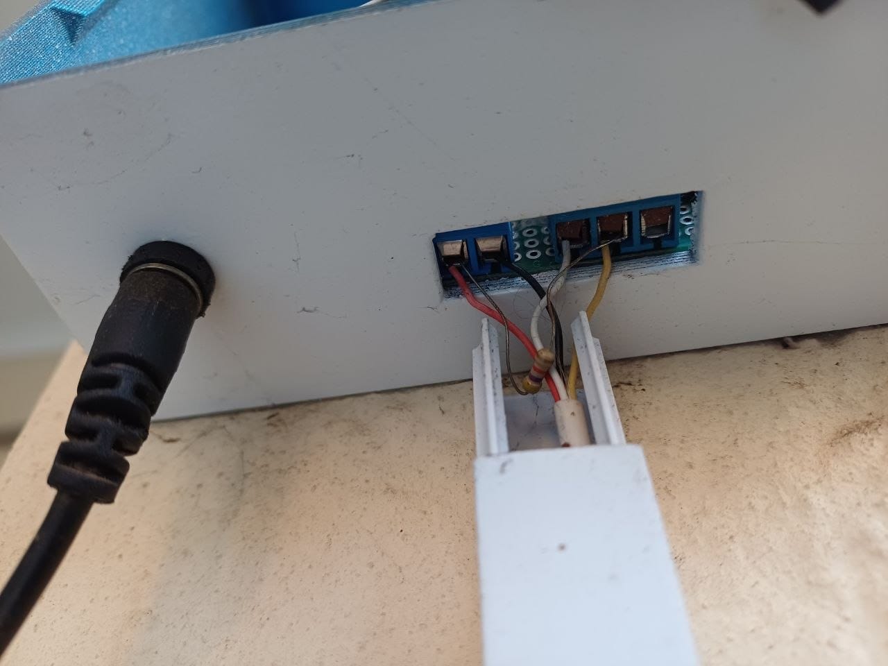
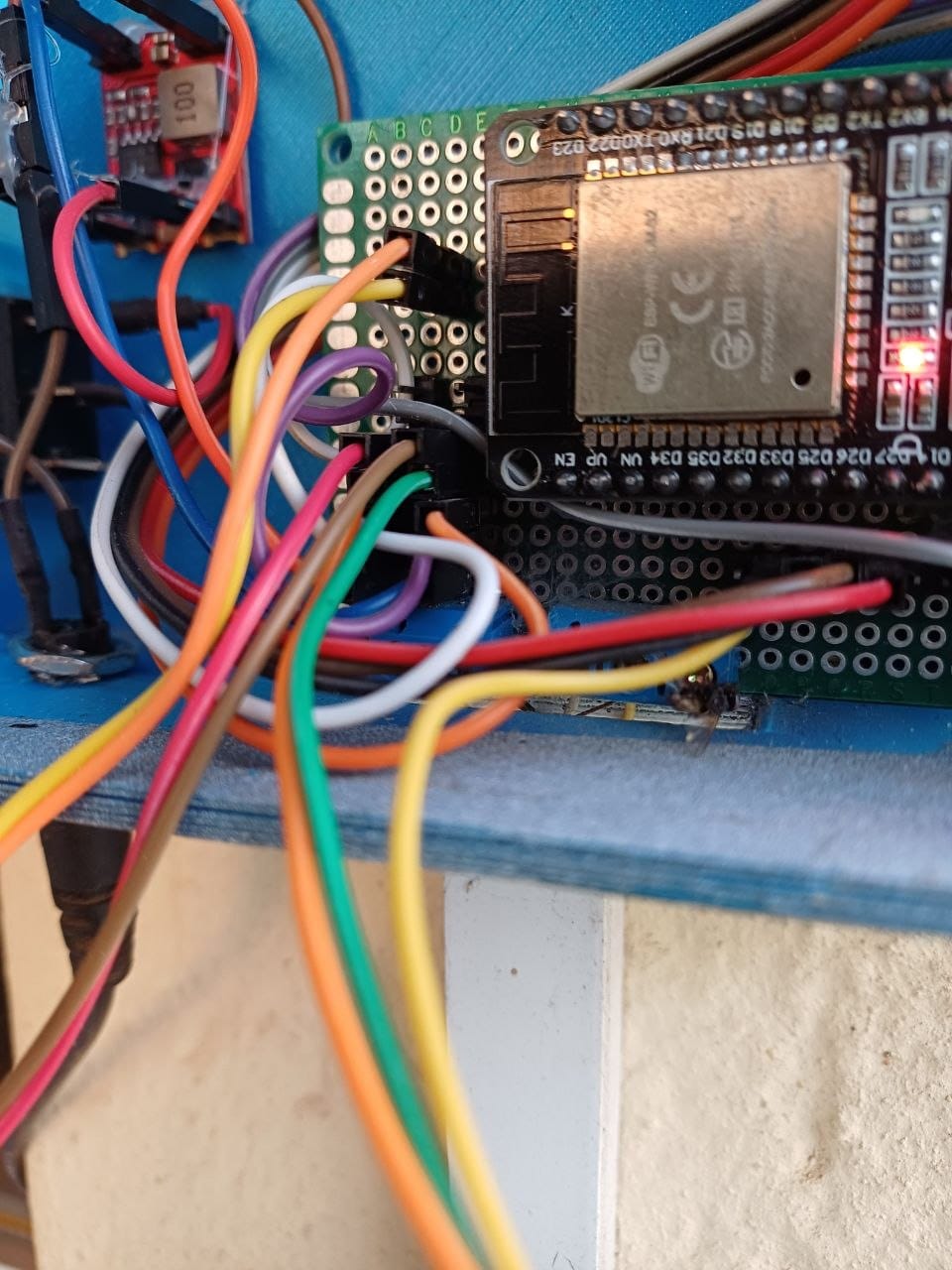
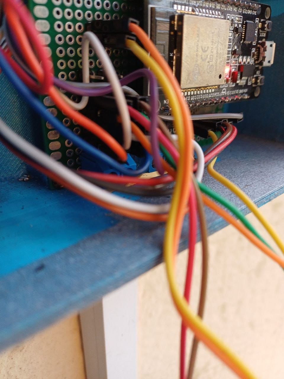
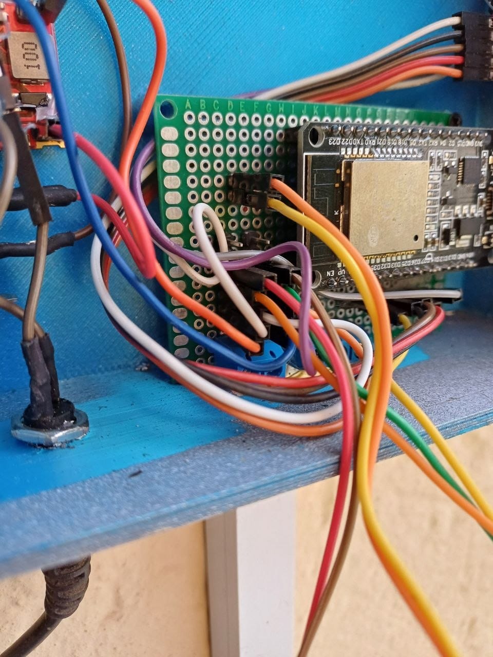
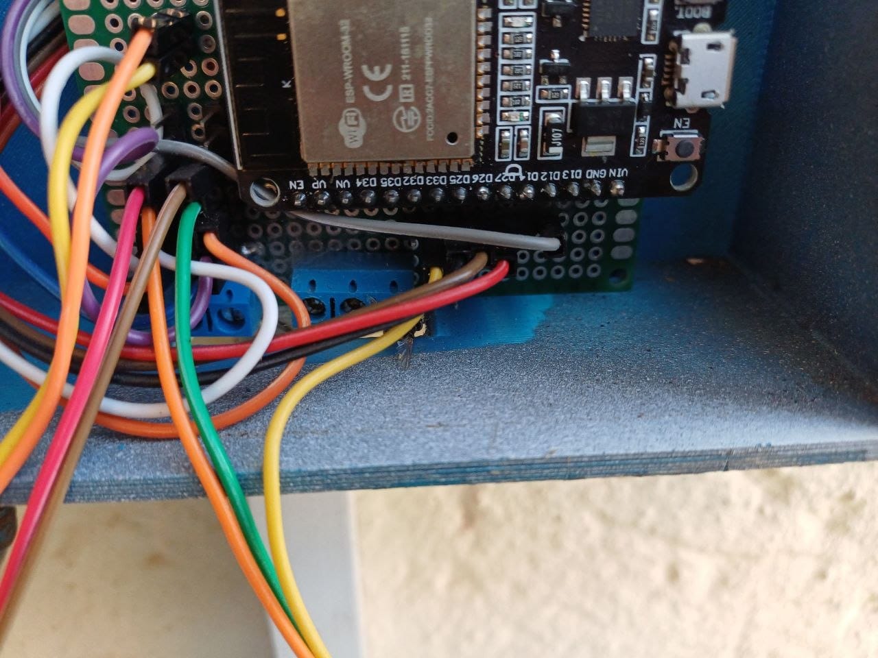
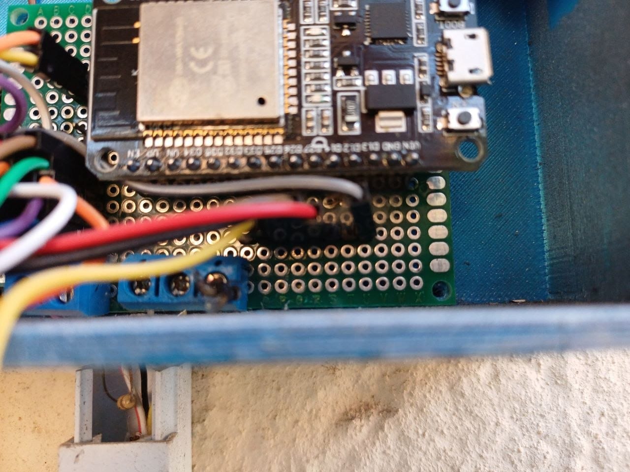
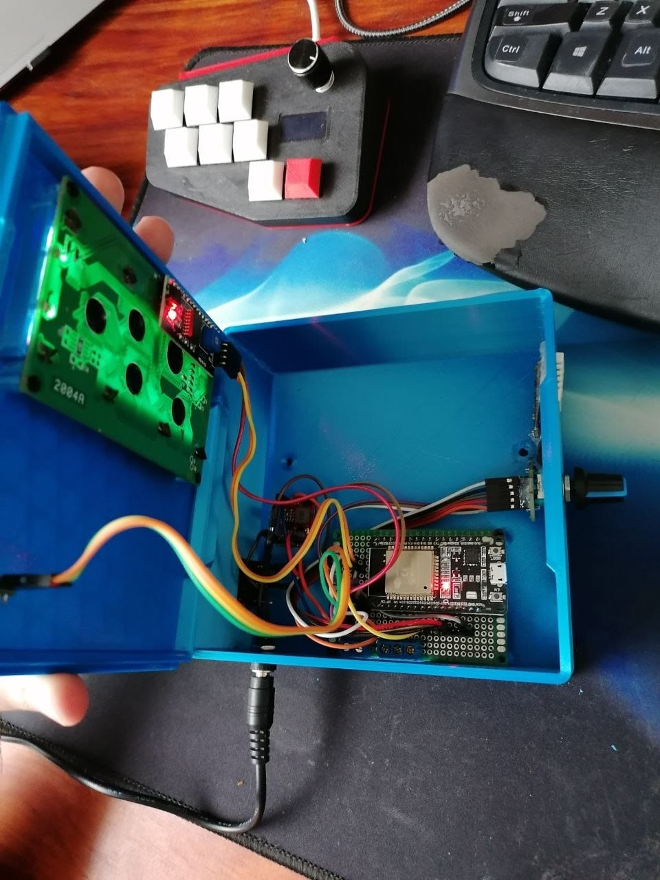
Before I took it off the wall, I photographed the inside of it. I wanted a record of where every wire went, mostly as insurance in case I ended up rebuilding the board and could not remember how any of it had been connected. That turned out to be one of the better decisions I made in this whole project. The blue you can see inside it is the bare print, by the way — this is the same box from the wall photos further up, and I only ever painted the outside, because the inside is not the part that has to survive the sun.
Those photos also settled something I had been getting wrong. The module on the board is an ESP32-WROOM-32 — a plain, ordinary classic ESP32, which is exactly what the sketch means when it says board: esp32dev. No exotic variant, no special chip, just the standard devkit that has been sitting in that box this whole time.
The last try that worked
So I stripped the PCB out and took it to my workbench, and I made peace with the fact that I might have to rebuild the whole board. Different GPIO pins, different component placement, everything I have learned since 2023.
Before I did that, I gave it one more go: I updated and modified the ESPHome sketch a bit, and then put it all back together on the bench using spare sensors I had lying around, purely to test one more time.
It worked.
I then spent the time getting the code and the functionality back to a complete working model — the sensors reading properly, the display doing its job, the data going where it should. Then I screwed the PCB back into its fixed position in the box, which was the whole point of the exercise, and it still worked.
And here is the honest part: I still cannot tell you which thing fixed it. Years of debugging, a custom 3D printed box, a new firmware stack, a rebuilt sketch — somewhere in there the problem went away, and I do not have the clean before-and-after that would tell me why. If you are hoping this post ends with “and it turned out to be X”, I am sorry to disappoint you. What I can tell you is that it works inside a closed box now, which it had not done since 2023.
What the screen shows now
Four lines, and it is worth spelling out exactly what is on them, because this is what we actually walk past and read:
- Line 1: the date and time — Thu 24 Sep 18:15. The clock came back too, but not the way it worked in 2023: the sketch now takes its time from Home Assistant instead of hitting an NTP server itself. Same clock the rest of the house runs on.
- Line 2: the pool temperature, from the DS18B20 in the water.
- Line 3: air temperature and humidity, from the DHT22.
- Line 4: the water level, reading either Full or Low off the float sensor.
And the PIR still does the only job I ever gave it: walk up and the backlight comes on, walk away and it goes off again thirty seconds later.
On the afternoon I sat down to write this, that screen was reading 23°C in the pool, 32.7°C in the air at 41% humidity, and a full water level. That is the whole argument for the project sitting on one screen — 23 degrees is a decision you can make with your eyes on the way past, and you do not need an app for it.
What I let go of on purpose
The menus and the rotary encoder are gone. Not because they broke — because I would never have used them.
Building custom menus with my own code was the most fun part of this project, and I have no regrets about the days I spent on it. But the honest truth is that I do not walk up to a box on the wall next to a swimming pool to browse a menu and switch on the lights. I walk up to it to see whether the pool is warm enough to get in.
What I actually want from this device is the stats on the screen where we pass it, and the data in Home Assistant. From there I can alert when the pool is nice and warm for a swim, and alert when the water is low. Topping up is still something I do by hand for now, but that was never meant to be permanent: it was always going to run itself, with a manual override for when I want control instead. What I am doing at the moment is making certain the level reporting is honest before I let it act on that on its own. That is the version that earned its place back on the wall.
Why I put it back at all
While it was on my workbench, I seriously considered finishing it off differently: leaving the project dead, or pulling the whole thing off the wall and pretending it never happened.
It sat on my desk like that for a few days. And what changed my mind was noticing how often someone glances at that screen on the way past. Not opening an app, not asking a voice assistant — just looking at it. We used it far more than I remembered using it.
So it had to survive if I could possibly make it survive. And with the AI tools we have available now, I could finally get it back to being a genuinely working project. A chunk of that was unglamorous: the sketch had drifted badly out of date since 2023. Options that used to sit on the sensor itself had moved under the pin: block in newer ESPHome versions, and getting all of that straightened out was half the work of bringing it back to life — not just living with what I had, which is what I had been doing for years.
The ESPHome sketch
Here it is in full, exactly what is running on the device. The only things you need to change are the Wi-Fi secrets and, if your LCD is blank, the I2C address:
esphome:
  name: pool-temp-monitor
  friendly_name: Pool Monitor

esp32:
  board: esp32dev

logger:
api:
ota:
  - platform: esphome

wifi:
  ssid: !secret wifi_ssid
  password: !secret wifi_password

# Sync clock directly with Home Assistant
time:
  - platform: homeassistant
    id: ha_time

# 1. Initialize I2C Bus for the LCD
i2c:
  sda: GPIO21
  scl: GPIO22
  scan: true
  id: bus_a

# 2. Initialize 1-Wire Bus for DS18B20
one_wire:
  - platform: gpio
    pin: GPIO14
    id: hub_1wire

# 3. Binary Sensors (Water Float, PIR, Rotary Push Button)
binary_sensor:
  - platform: gpio
    pin:
      number: GPIO33
      mode: INPUT
    name: "PIR Motion Sensor"
    id: pir_motion_sensor
    device_class: motion
    # Automatically control the LCD backlight when motion changes
    on_state:
      then:
        - if:
            condition:
              binary_sensor.is_on: pir_motion_sensor
            then:
              - lambda: id(my_display).backlight();
            else:
              - delay: 30s
              - if:
                  condition:
                    binary_sensor.is_off: pir_motion_sensor
                  then:
                    - lambda: id(my_display).no_backlight();

  - platform: gpio
    pin:
      number: GPIO32
      mode: INPUT_PULLUP
      inverted: false  # Correct modern nesting under pin definition
    name: "Water Float Switch"
    id: water_float_switch
    internal: true

  - platform: gpio
    pin:
      number: GPIO25
      mode: INPUT_PULLUP
      inverted: true  # Correct modern nesting under pin definition
    name: "Rotary Encoder Button"
    id: encoder_button
    on_press:
      then:
        - logger.log: "Rotary Encoder Pressed"

text_sensor:
  - platform: template
    name: "Water Level Status"
    id: water_level_text
    icon: "mdi:water-boiler"
    update_interval: 1s
    lambda: |-
      if (id(water_float_switch).state) {
        return std::string("Full");
      } else {
        return std::string("Low");
      }

# 4. Sensors (DHT22, DS18B20, Rotary Encoder Counter)
sensor:
  - platform: dht
    pin: GPIO13
    model: DHT22
    temperature:
      name: "DHT22 Temperature"
      id: dht22_temp
    humidity:
      name: "DHT22 Humidity"
      id: dht22_hum
    update_interval: 15s

  - platform: dallas_temp
    one_wire_id: hub_1wire
    name: "DS18B20 Temperature"
    id: ds18b20_temp
    update_interval: 15s

  - platform: rotary_encoder
    name: "Rotary Encoder Dial"
    pin_a:
      number: GPIO26
      mode: INPUT_PULLUP
    pin_b:
      number: GPIO27
      mode: INPUT_PULLUP
    id: encoder_dial

# 5. Display Configuration (20x4 Liquid Crystal Display via I2C)
display:
  - platform: lcd_pcf8574
    dimensions: 20x4
    address: 0x3F  # Adjust to 0x3F if display remains blank
    id: my_display
    lambda: |-
      // Row 0: Date & Time (Thu 24 Sep 18:15)
      auto time_now = id(ha_time).now();
      if (time_now.is_valid()) {
        it.strftime(0, 0, "%a %d %b %H:%M    ", time_now);
      } else {
        it.print(0, 0, "Time: Syncing...    ");
      }

      // Row 1: DS18B20 Pool Temp (Moved down)
      if (id(ds18b20_temp).has_state()) {
        it.printf(0, 1, "Pool Temp: %.1fC    ", id(ds18b20_temp).state);
      } else {
        it.print(0, 1, "DS18: Loading...    ");
      }

      // Row 2: DHT22 Air Temp & Humidity (Moved down)
      if (id(dht22_temp).has_state() && id(dht22_hum).has_state()) {
        it.printf(0, 2, "Air Temp: %.1fC %.0f%% ", id(dht22_temp).state, id(dht22_hum).state);
      } else {
        it.print(0, 2, "DHT: Loading...     ");
      }

      // Row 3: Water Level Status (Moved down)
      if (id(water_level_text).has_state()) {
        it.printf(0, 3, "Water Level: %-7s", id(water_level_text).state.c_str());
      } else {
        it.print(0, 3, "Water Level: Check..");
      }
Two notes for anyone copying this. The !secret values are just Wi-Fi credentials sitting in a separate secrets.yaml — nothing clever. And the I2C address is 0x3F, which is what my LCD reports; plenty of these boards come in at 0x27, so run an I2C scan if yours stays dark. The encoder and its pins are still declared down at the bottom of it. I left them in — it costs me nothing to leave them there, and if I ever do press that knob it will dutifully shout about it in the logs and do absolutely nothing else.
What I would tell anyone building one
- An enclosure is part of the circuit, not a box you put it in afterwards. It worked on the breadboard, it worked on my own PCB, and it stopped working the moment I closed the lid. If I had tested it inside the box earlier, I would have saved myself a very long year.
- Do not fall in love with a feature you will never use. The menus were the best fun in the build and the first thing I cut when the project became about actually being used.
- Get the reporting right before you automate on top of it. I could wire that float sensor to the fill valve this afternoon, but I would rather watch it report honestly for a while first. Automating on a sensor you do not yet trust is how you end up with a pool you still have to go and check on.
- A display you walk past is worth more than you think. The reason this project survived was not what it could do, it was where it was.
- You are allowed to be annoyed by something that works. This ran for years doing its job, and I was never happy with it. Being unhappy with it is what eventually got it fixed.
The build, in pictures
These are all from the 2023 build, so they show the project at every stage of its first life, and there are three boxes in them, so here is the key. The blue one is the 3D printed enclosure I designed to move the ESP32 out from under the LCD, shown both as raw parts straight off the printer and with everything fitted. The white one is that same printed enclosure after I painted it — which is the version that ended up going on the wall, complete with the rotary encoder still on the front and the menu system still working on the screen. And the small black box was the off-the-shelf project box I started with before any of the printing.
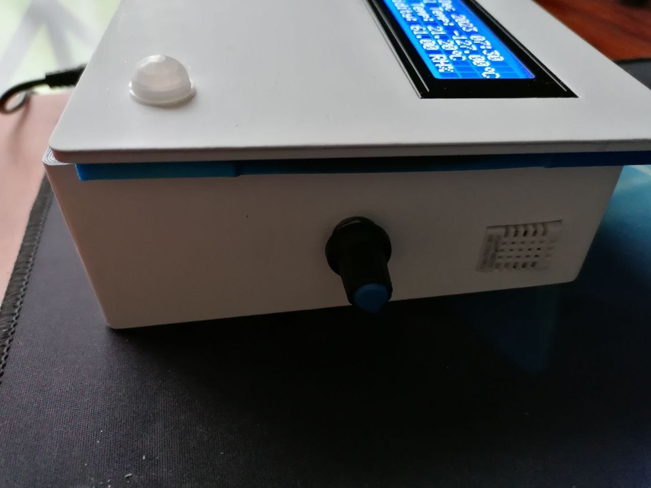
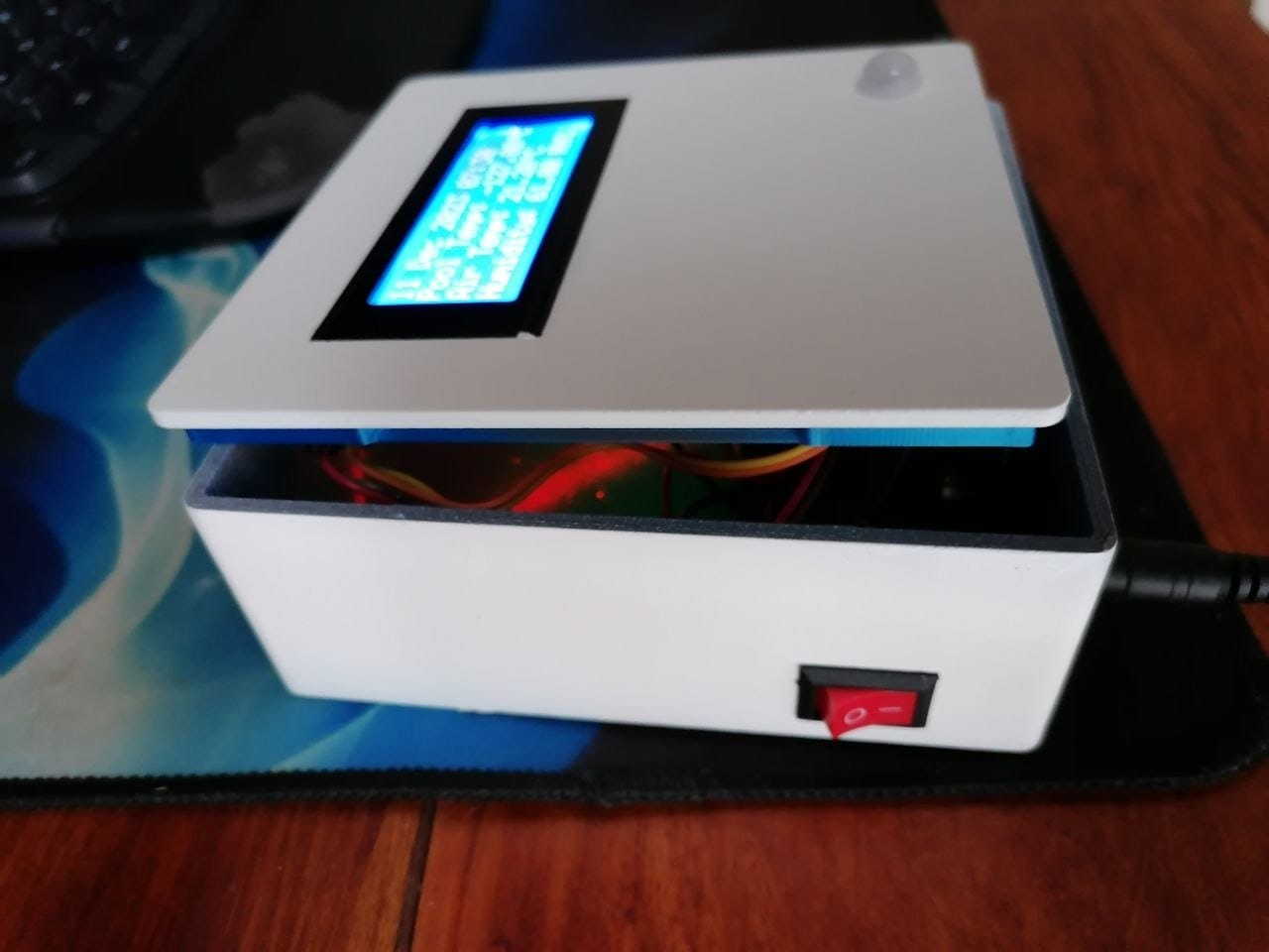
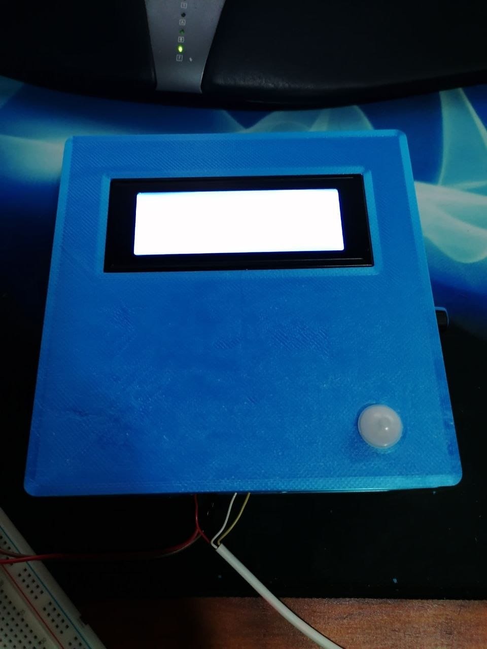
That last photo is the compromise version, by the way — pool, air and humidity, three lines, no clock, and it stayed like that for years.